こちらはこの章のコード例です。これらのページは現在、時間をかけて更新されています(画像、キャプションの追加、おそらくさらなる例の追加)。更新のためにもう一度訪れてください。もちろん、このページを説明が得られる本と一緒に使用するのが最善の方法です。

図 4.1 – 二つのノードを接続する基本的なエッジ
\documentclass[border=10pt]{standalone}
\usepackage{tikz}
\usetikzlibrary{positioning}
\begin{document}
\begin{tikzpicture}
  \node (tex) [fill=orange, text=white] {TEX};
  \node (pdf) [fill={rgb:red,244;green,15;blue,2},
    text=white, right=of tex] {PDF};
  \draw (tex) edge[->] (pdf);
\end{tikzpicture}
\end{document}

図 4.2 – テキストラベル付きエッジ
\documentclass[border=10pt]{standalone}
\usepackage{tikz}
\usetikzlibrary{positioning}
\begin{document}
\begin{tikzpicture}
  \node (tex) [fill=orange, text=white] {TEX};
  \node (pdf) [fill={rgb:red,244;green,15;blue,2},
    text=white, right=of tex] {PDF};
  \draw (tex) edge[->] node[font=\tiny\ttfamily,above] {pdflatex} (pdf);
\end{tikzpicture}
\end{document}
With quotes syntax:
\documentclass[border=10pt]{standalone}
\usepackage{tikz}
\usetikzlibrary{positioning,quotes}
\begin{document}
\begin{tikzpicture}
  \node (tex) [fill=orange, text=white] {TEX};
  \node (pdf) [fill={rgb:red,244;green,15;blue,2},
    text=white, right=of tex] {PDF};
  \draw (tex)
    edge["pdflatex" {font=\ttfamily\tiny,above},->] (pdf);
\end{tikzpicture}
\end{document}
With style definitions:
\documentclass[border=10pt]{standalone}
\usepackage{tikz}
\usetikzlibrary{positioning,quotes}
\begin{document}
\begin{tikzpicture}[
    every node/.style={font=\large,text=white},
    every edge/.style={draw,->},
    every edge quotes/.style={auto,font=\ttfamily\tiny,text=black,fill=none}
  ]
  \node (tex) [fill=orange] {TEX};
  \node (pdf) [fill={rgb:red,244;green,15;blue,2},right=of tex] {PDF};
  \draw (tex) edge["pdflatex"] (pdf);
\end{tikzpicture}
\end{document}
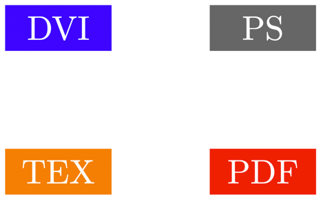
図 4.3 – 四つのノード
\documentclass[border=10pt]{standalone}
\usepackage{tikz}
\usetikzlibrary{positioning,quotes}
\begin{document}
\begin{tikzpicture}[
    every node/.style = {text=white, minimum width = 1.1cm},
    every edge/.style = {draw,->},
    every edge quotes/.style = {auto, font=\tiny\ttfamily, text=black}]
  ]
  \node (tex) [fill=orange] {TEX};
  \node (pdf) [fill={rgb:red,244;green,15;blue,2}, right = of tex] {PDF};
  \node (dvi) [fill=blue, above = of tex] {DVI};
  \node (ps)  [fill=black!60,above = of pdf] {PS};
\end{tikzpicture}
\end{document}
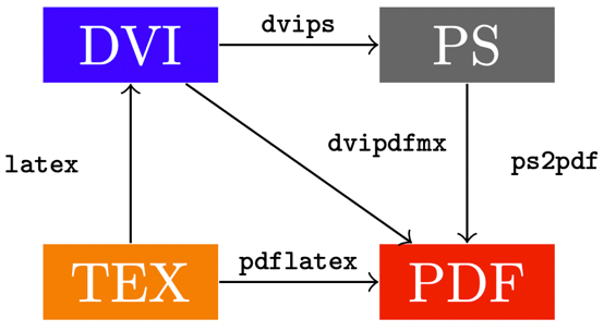
図 4.4 – 多くのエッジにテキストがあります
\documentclass[border=10pt]{standalone}
\usepackage{tikz}
\usetikzlibrary{positioning,quotes}
\begin{document}
\begin{tikzpicture}[
    every node/.style = {text=white, minimum width = 1.1cm},
    every edge/.style = {draw,->},
    every edge quotes/.style = {auto, font=\tiny\ttfamily, text=black}]
  ]
  \node (tex) [fill=orange] {TEX};
  \node (pdf) [fill={rgb:red,244;green,15;blue,2},right = of tex] {PDF};
  \node (dvi) [fill=blue, above = of tex] {DVI};
  \node (ps)  [fill=black!60, above = of pdf] {PS};
  \draw (tex) edge["pdflatex"] (pdf);
  \draw (tex) edge["latex"]    (dvi);
  \draw (dvi) edge["dvips"]    (ps);
  \draw (dvi) edge["dvipdfmx"] (pdf);
  \draw (ps)  edge["ps2pdf"]   (pdf);
\end{tikzpicture}
\end{document}
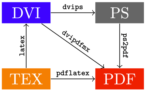
図 4.5 – エッジ上の斜めテキスト
\documentclass[border=10pt]{standalone}
\usepackage{tikz}
\usetikzlibrary{positioning,quotes}
\begin{document}
\begin{tikzpicture}[
    every node/.style = {font=\large, text=white},
    every edge/.style = {draw, ->},
    every edge quotes/.style = {auto, font=\ttfamily\tiny,
      text=black, fill=none, sloped}]
  \node (tex) [fill = orange] {TEX};
  \node (pdf) [fill = {rgb:red,244;green,15;blue,2}, right = of tex] {PDF};
  \node (dvi) [fill = blue, above = of tex] {DVI};
  \node (ps)  [fill = black!60, above = of pdf] {PS};
  \draw (tex) edge["pdflatex"] (pdf);
  \draw (tex) edge["latex"]    (dvi);
  \draw (dvi) edge["dvips"]     (ps);
  \draw (ps)  edge["ps2pdf"]   (pdf);
  \draw (dvi) edge["dvipdfmx"] (pdf);
\end{tikzpicture}
\end{document}
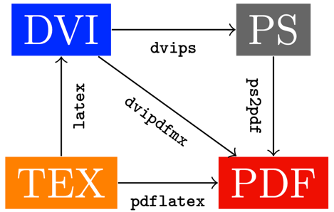
図 4.6 – オート=ライトオプションを持つ斜めテキスト
\documentclass[border=10pt]{standalone}
\usepackage{tikz}
\usetikzlibrary{positioning,quotes}
\begin{document}
\begin{tikzpicture}[
    every node/.style = {font=\large, text=white},
    every edge/.style = {draw, ->},
    every edge quotes/.style = {auto=right, font=\ttfamily\tiny,
      text=black, fill=none, sloped}]
  \node (tex) [fill = orange] {TEX};
  \node (pdf) [fill = {rgb:red,244;green,15;blue,2}, right = of tex] {PDF};
  \node (dvi) [fill = blue, above = of tex] {DVI};
  \node (ps)  [fill = black!60, above = of pdf] {PS};
  \draw (tex) edge["pdflatex"] (pdf);
  \draw (tex) edge["latex"]    (dvi);
  \draw (dvi) edge["dvips"]     (ps);
  \draw (ps)  edge["ps2pdf"]   (pdf);
  \draw (dvi) edge["dvipdfmx"] (pdf);
\end{tikzpicture}
\end{document}
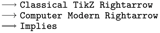
図 4.7 – 数学的矢印
\documentclass[border=10pt]{standalone}
\usepackage{tikz}
\usetikzlibrary{arrows.meta}
\begin{document}
\begin{tikzpicture}[yscale=-1, y=2.5ex]
  \foreach \tip [count=\i] in {
    Classical TikZ Rightarrow, Computer Modern Rightarrow
  } {
    \draw [-{\tip}] (0, \i) to ++(0.5, 0)
      node [right] {\texttt{\tip}};
  }
  \draw [-{Implies}, double, yshift=2.2em] (0,1) to ++(0.5, 0)
    node [right] {\texttt{Implies}};
\end{tikzpicture}
\end{document}
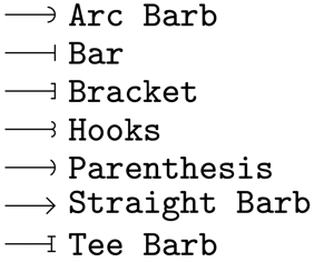
図 4.8 – バーブド矢印
\documentclass[border=10pt]{standalone}
\usepackage{tikz}
\usetikzlibrary{arrows.meta}
\begin{document}
\begin{tikzpicture}[yscale=-1, y=2.5ex]
  \foreach \tip [count=\i] in {
    Arc Barb, Bar, Bracket, Hooks, Parenthesis,
    Straight Barb, Tee Barb
  } {
    \draw [-{\tip}] (0, \i) to ++(0.5, 0)
      node [right] {\texttt{\tip}};
  }
\end{tikzpicture}
\end{document}
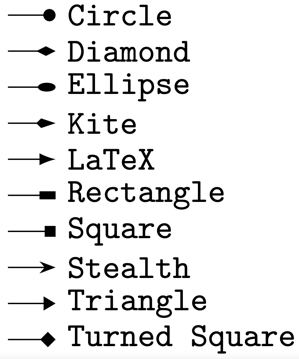
図 4.9 – 幾何学的矢印
\documentclass[border=10pt]{standalone}
\usepackage{tikz}
\usetikzlibrary{arrows.meta}
\begin{document}
\begin{tikzpicture}[yscale=-1, y=2.5ex]
  \foreach \tip [count=\i] in {
    Circle, Diamond, Ellipse, Kite, Latex, Latex[round],
    Rectangle, Square, Stealth, Stealth[round],
    Triangle, Turned Square
  } {
    \draw [-{\tip}] (0, \i) to ++(0.5, 0)
      node [right] {\texttt{\tip}};
  }
\end{tikzpicture}
\end{document}
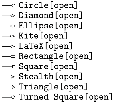
図 4.10 – オープン幾何学的矢印
\documentclass[border=1pt]{standalone}
\usepackage{tikz}
\usetikzlibrary{arrows.meta}
\begin{document}
\begin{tikzpicture}[yscale=-1, y=2.5ex]
  \foreach \tip [count=\i] in {
    Circle[open], Diamond[open], Ellipse[open], Kite[open],
    Latex[open], Rectangle[open], Square[open], Stealth[open],
    Triangle[open], Turned Square[open]
  } {
    \draw [-{\tip}] (0, \i) to ++(0.5, 0)
      node [right] {\texttt{\tip}};
  }
\end{tikzpicture}
\end{document}

図 4.11 – カスタマイズされた矢印の先端
\documentclass[border=10pt]{standalone}
\usepackage{tikz}
\usetikzlibrary{positioning,arrows.meta}
\begin{document}
\begin{tikzpicture}
  \node (tex) [fill=orange, text=white] {TEX};
  \node (pdf) [fill={rgb:red,244;green,15;blue,2},
    text=white, right=of tex] {PDF};
  \draw (tex) edge[very thick, draw=red,
    -{Stealth[color=orange, fill=red, width=8pt, length=10pt]}]
    (pdf);
\end{tikzpicture}
\end{document}

図 4.12 – 矢印の先端を持つ曲線
\documentclass[border=10pt]{standalone}
\usepackage{tikz}
\usetikzlibrary{positioning}
\begin{document}
\begin{tikzpicture}
  \node (tex) [fill=orange, text=white] {TEX};
  \node (pdf) [fill={rgb:red,244;green,15;blue,2},
    text=white, right=of tex] {PDF};
  \draw[->] (tex) to[out=45, in=225, looseness=1.5] (pdf);
\end{tikzpicture}
\end{document}
–, to, および edge の比較
\documentclass[border=10pt]{standalone}
\usepackage{tikz}
\usetikzlibrary{positioning}
\begin{document}
\begin{tikzpicture}
  \node (1) {1};
  \node (2) [right = of 1] {2};
  \node (3) [right = of 2] {3};
  \draw[->] (1) -- (2)
            (2) -- (3);
  \node (4) [below = of 1] {1};
  \node (5) [right = of 4] {2};
  \node (6) [right = of 5] {3};
  \draw [->] (4) to (5)
             (5) to (6);
  \node (7) [below = of 4] {1};
  \node (8) [right = of 7] {2};
  \node (9) [right = of 8] {3};
  \draw[->, color=red, very thick] (7) edge (8)
            (8) edge (9);
\end{tikzpicture}
\end{document}
図 4.13 – 望ましくない矢印の先端
コメント:
エッジ操作では別のパスが作成されるため、エッジオプションとして矢印を使用しますが、矢印は引き継がれます。しかし、ここで何が起こるか見てください:
\documentclass[tikz,border=10pt]{standalone}
\begin{document}
\begin{tikzpicture}
  \draw[->]  (0,0) edge (1,0);
\end{tikzpicture}
\end{document}
パスの始まりに望ましくない矢印があります。
次の章 へ進む.